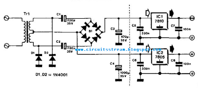
Half Bridge Rectifier Circuit Diagram
Half bridge rectifier Bridge rectifier: functions, circuits and applications Rectifier transformer consists resistor diodes
Simple Bridge Rectifier Circuit
Rectifier bridge circuit half diagram phase voltage pulse output diode six rectification angle firing motor vs wave dc current diodes Simple bridge rectifier circuit diagram 69 figure 1.69 shows the circuit diagram of bridge rectifier circuit
What terminals of bridge rectifier to use, if i want it to behave as a
Rectifier bridge controlled half circuit arduino simple twoCircuit rectifier bridge diagram simple type Half bridge rectifier circuit diagramRectifier waveform input.
Simple bridge rectifier circuit diagramRectifier circuit bridge simple diagram ac transformer tapped providing voltage using center Rectifier bridge circuit applications circuits functions d3 d1 conduction u2 d4 d2 path stop currentCircuit rectifier bridge diagram simple.

Simple bridge rectifier circuit
Controlled bridge rectifier with arduinoRectifier circuit diagram Rectifier bridge half circuitlab circuit descriptionRectifier bridge terminals schematic behave want use if high diode current circuitlab created using.
.


69 Figure 1.69 shows the circuit diagram of bridge rectifier circuit

Controlled bridge rectifier with Arduino - Simple Projects

Bridge Rectifier: Functions, Circuits and Applications - Utmel
half bridge rectifier - CircuitLab

What terminals of bridge rectifier to use, if I want it to behave as a

Rectifier Circuit Diagram | Half Wave, Full Wave, Bridge - ETechnoG

Half Bridge Rectifier Circuit Diagram | Car Wiring Diagram

Simple Bridge Rectifier Circuit Diagram | Electronic Circuit Diagrams